Power King T92 3-Speed Transmission Rebuild Overhaul, Part 3 — Assembling the T92 Transmission

Previously in this series of articles, we have covered the teardown of a T92 transmission for rebuild in Part 1, and removed & installed front and rear ball bearings in Part 2.

This is Part 3, covering assembly of the T92 transmission gearbox. Let’s get to it. First, here’s an exploded view and illustrated parts list (IPL).

I’m assuming you have a nice clean transmission case, and all your parts are ready to go. There should already be a snap ring inside the rear of the case, for the front of the rear bearing to butt up against.

Empty T92 Borg-Warner transmission case.
(Photo © Russ Chastain)

Start with the reverse idler gear and it shaft. The front of the gear will probably be tapered slightly from wear; that’s okay.

Reverse idler gear and its shaft.
(Photo © Russ Chastain)

Place the gear where it belongs, and insert the shaft from the back side of the case — making sure the retainer slot is positioned correctly.

This is where the reverse idler gear belongs.
(Photo © Russ Chastain)

When you start the shaft, make sure the slot is facing towards the other shaft so the retainer will fit into it.

Reverse idler shaft goes into this hole.
(Photo © Russ Chastain)

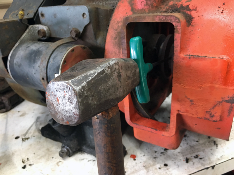
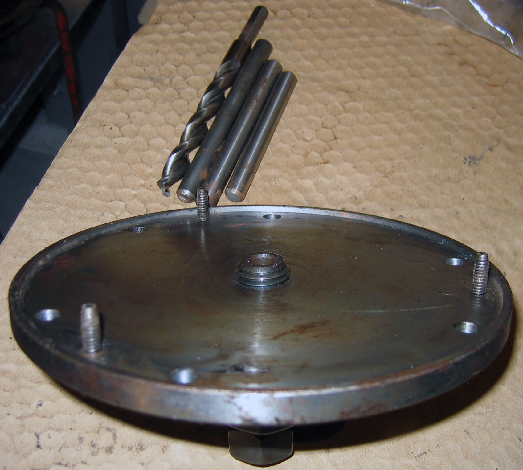
When you drive it in, make sure your punch is not above the slot. That will break the shaft, as you will see below.

Slot faces the retainer.
(Photo © Russ Chastain)

Next, place the cluster gear where it belongs. This one has more wear than I’d like to see; this is caused by grinding gears when shifting. The good news is, there’s still a lot of life left in it.

Cluster gear in place.
(Photo © Russ Chastain)

Run the shaft through the cluster gear, again making sure the slot is facing the correct direction.

Installing the cluster gear countershaft.
(Photo © Russ Chastain)

When you hit the shaft in the wrong place due to carelessness, you break it. If this was the reverse idler shaft, I’d have to trash it — or more likely, cut another slot 180 degrees from the old one. But the front bearing retainer will prevent this shaft from “walking” out the front, and the retainer will keep it from moving backwards. So I’ll just live with it.

Broken shaft retainer slot.
(Photo © Russ Chastain)

My usual practice is to use a cutoff wheel to cut new retainer slots into these shafts opposite the original slots, to allow the bushings inside the gears to ride on unworn portions of the shaft. I chose not to do that this time, because I was trying to retain the original tractor’s patina. And then I got stupid & broke the shaft! Derp.

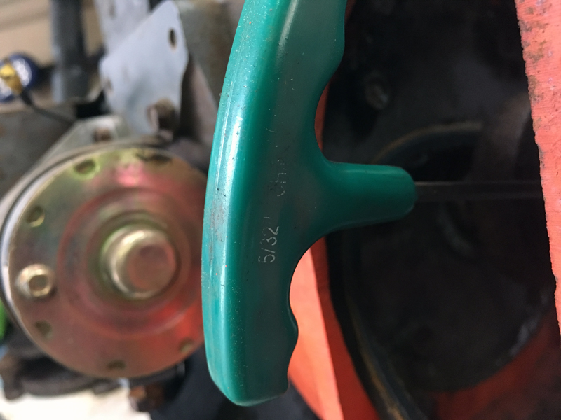
With shafts in place, slide the retainer (“lock shaft plate” in IPL) in place and start the 5/16″ cap screw with lock washer.

Retainer in place, screw ready to be tightened.
(Photo © Russ Chastain)

Tighten the retainer screw and you’re done with those lower shafts.

Tighten with a 1/2″ socket & extension.
(Photo © Russ Chastain)

Now for the main shaft. Don’t get hasty; you will need the main shaft with good bearing installed, both the sliding gears, and a snap ring.

Again — Make sure the inside snap ring is installed in the rear of the case. This will secure the front side of the rear bearing.

When you slide the main shaft into the transmission case, you’ll need to slide it through the sliding gears as you go.

You’ll need these parts to install the T92’s main shaft.
(Photo © Russ Chastain)

Hold the larger sliding gear in place with the shift fork slot towards the rear of the case, and slip the shaft into the case and through the gear.

Then slide the main shaft through the smaller sliding gear, keeping its shift fork slot towards the front of the case.

This photo shows how the gears should be arranged:

Main shaft in place with sliding gears.
(Photo © Russ Chastain)

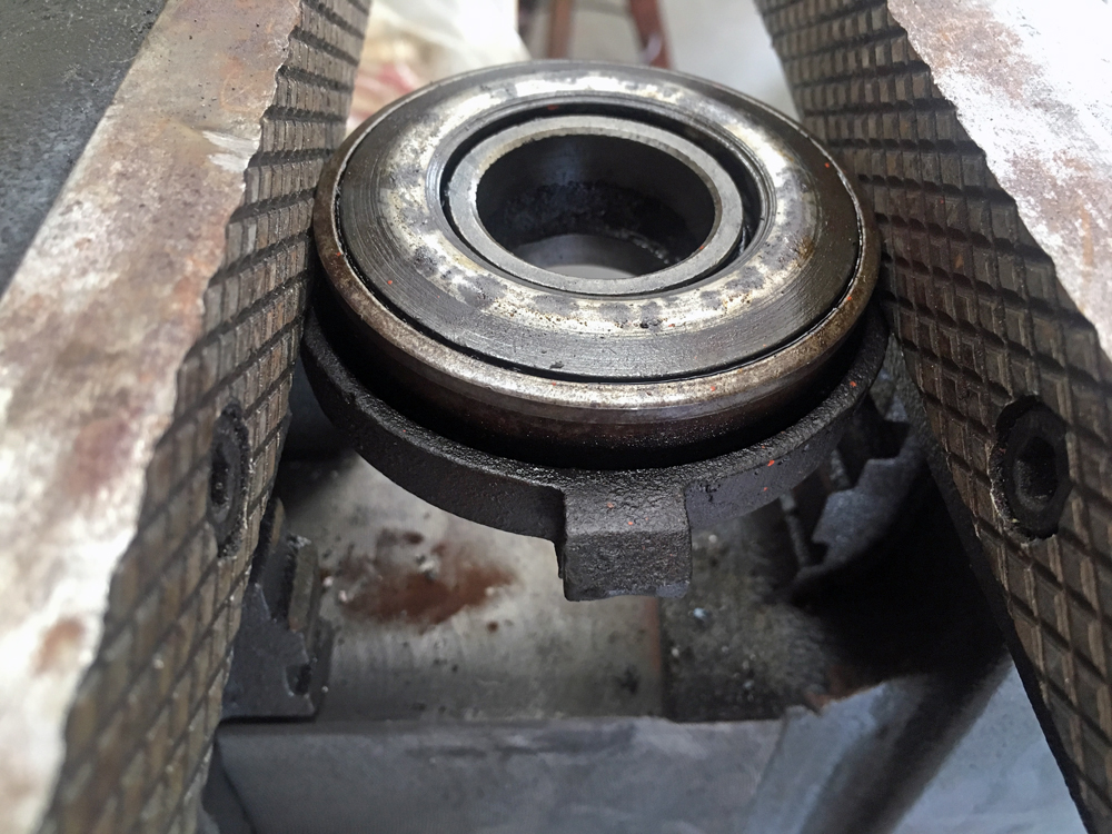
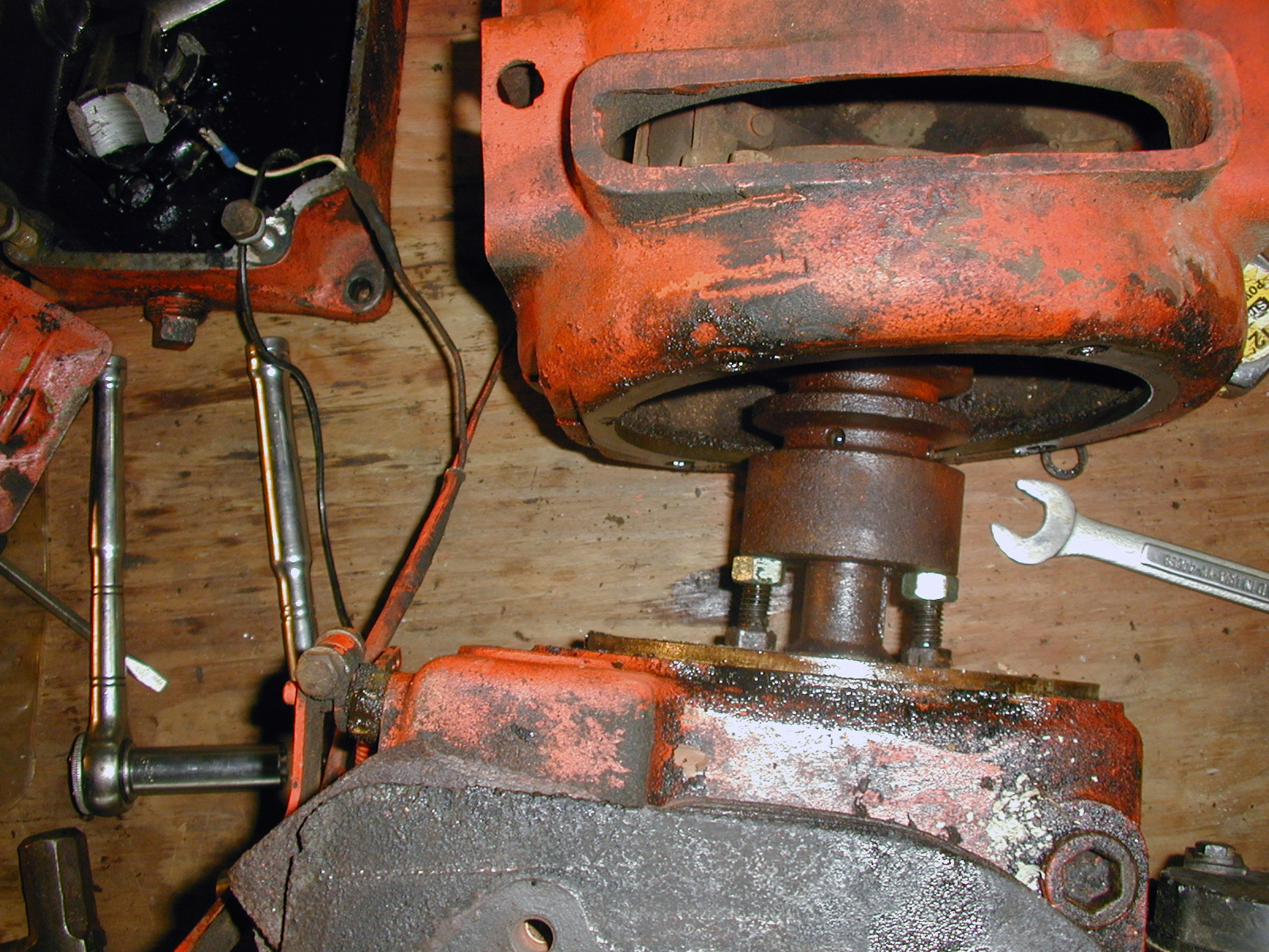
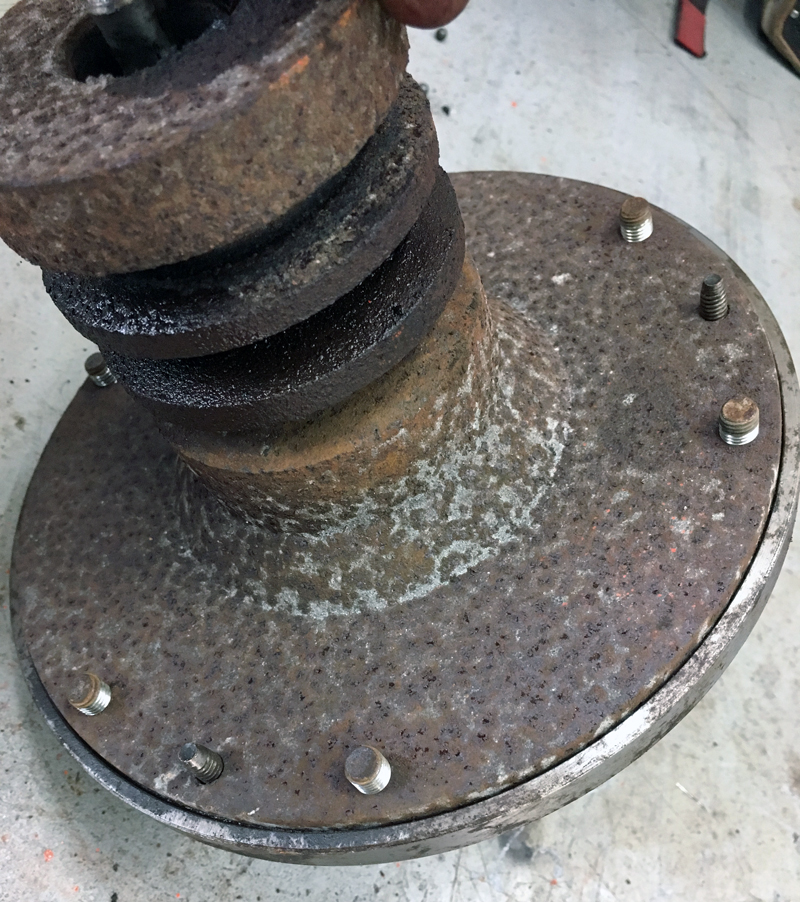
Make sure the rear bearing gets started straight in the case.

Rear bearing started nice and straight.
(Photo © Russ Chastain)

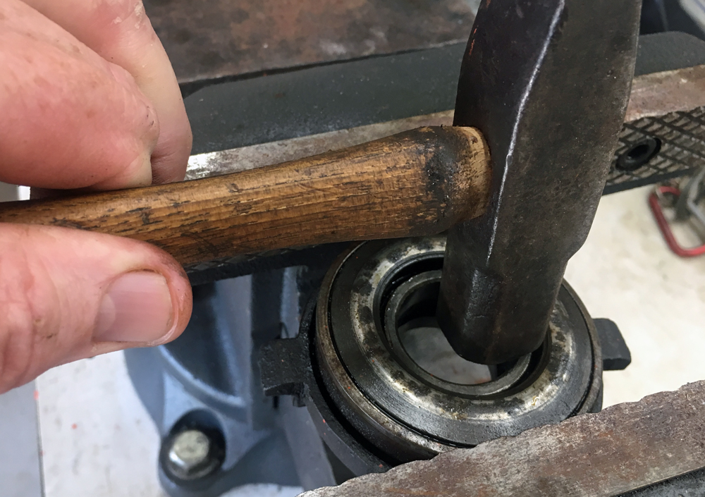
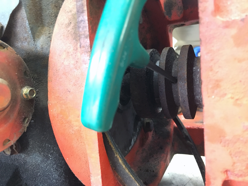
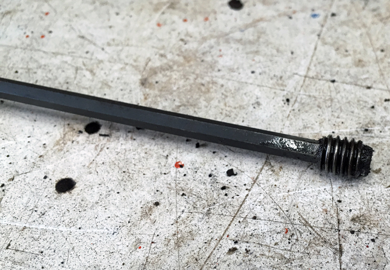
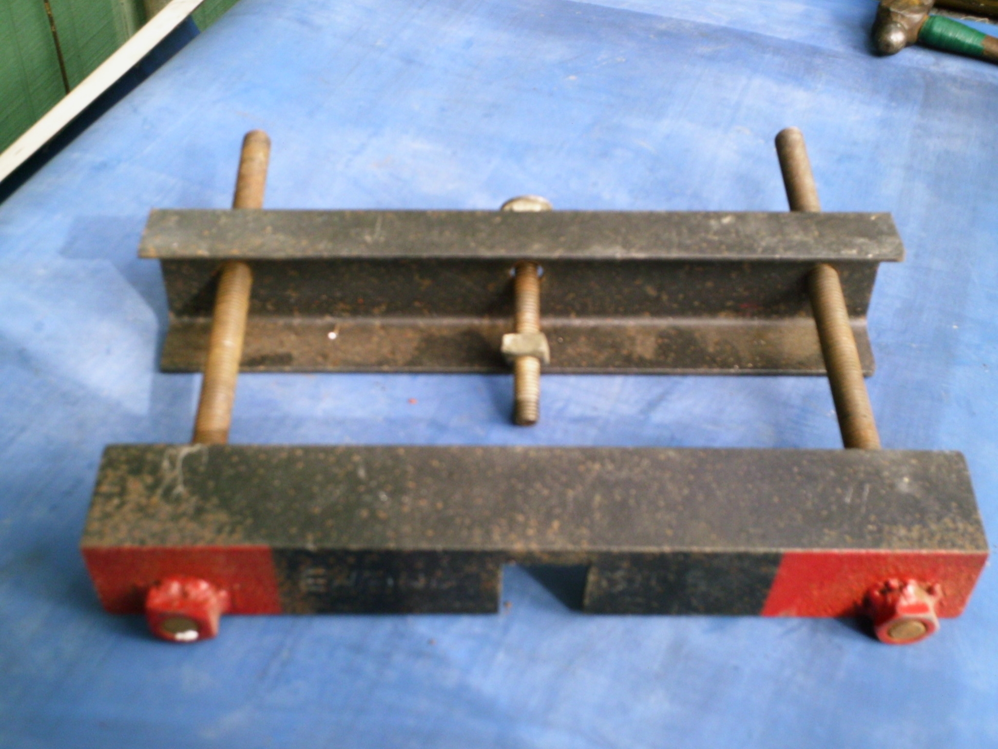
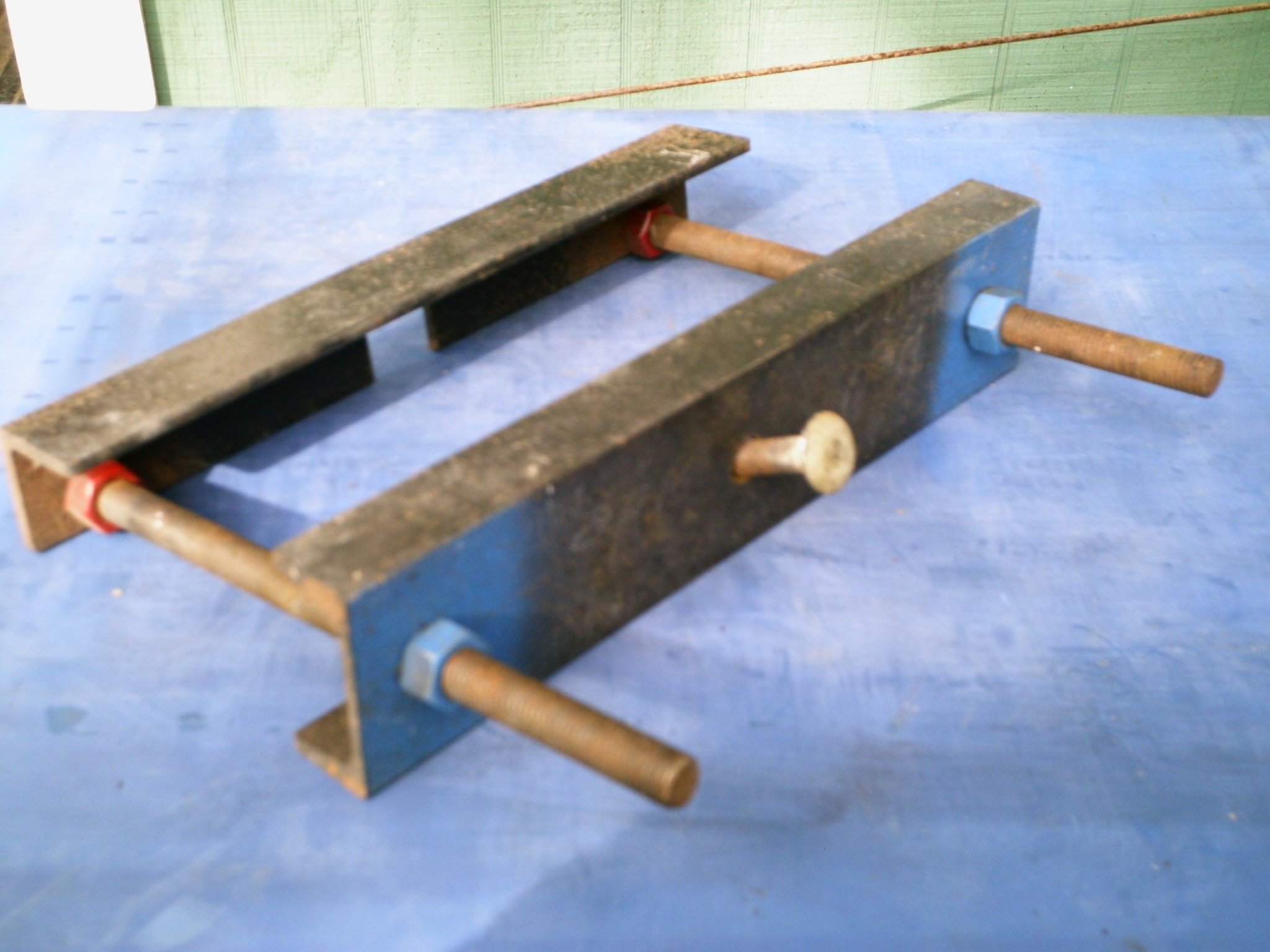
Use a tool, such as this old hunk of a Power King tie rod, to tap around the perimeter of the bearing to move it into place in the gear case.

Tap gently and keep moving the tool around the perimeter. The bearing will stop against the aforementioned front snap ring.

Keep an eye on the sliding gears while you do this, making sure they don’t slide too far forward on the shaft or get bound up somehow.

Use a tool to tap the bearing into place, moving the tool often.
(Photo © Russ Chastain)

Once the bearing is in place, check the sliding gears to make sure they are not binding anywhere and they can slide back & forth freely on the shaft.

Check to make sure the sliding gears are still free.
(Photo © Russ Chastain)

You want to be certain everything is good before you install the snap ring to secure the rear bearing.

Sliding gears should move freely on the shaft.
(Photo © Russ Chastain)

You know the bearing is properly positioned when the snap ring groove in the case is fully visible, as shown below.

Arrow indicates snap ring groove.
(Photo © Russ Chastain)

Now put the snap ring into the bore. It should be pretty easy to get it most of the way in there, keeping it pretty much parallel with the face of the bearing.

Snap ring partially in place.
(Photo © Russ Chastain)

Push one end of the snap ring down so it goes into the groove in the case. Then work a tool around the snap ring, moving the ring down a little at a time, “feeding” it into the groove.

One end of snap ring started in groove.
(Photo © Russ Chastain)

Work it on down until the entire snap ring is lying against the bearing and is properly fitted into the groove.

When you’re done, the snap ring will lie against the bearing all the way around, with both ends in the groove and even.
(Photo © Russ Chastain)

Time for the input shaft. Remember those 13 loose needle bearings from Part 1? It’s time to deal with those. The easiest way to do that is to stick them into the rear of the input shaft with some grease.

Grease!
(Photo © Russ Chastain)
Add a dab o’ grease, then a needle, repeat until you’re done.
(Photo © Russ Chastain)

Once you have the needle bearings safely secured, slip the rear end of the input shaft through the front of the gear case and over the front end of the main shaft.

Slipping the input shaft over the main shaft.
(Photo © Russ Chastain)

Your job here is to make sure all the needle bearings stay in place. The front bearing should slide into the gear case easily.

Input shaft properly assembled.
(Photo © Russ Chastain)

The snap ring on the outside of the front bearing should lie against the front of the transmission case like so:

Front bearing against front of transmission case.
(Photo © Russ Chastain)

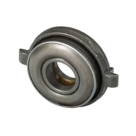
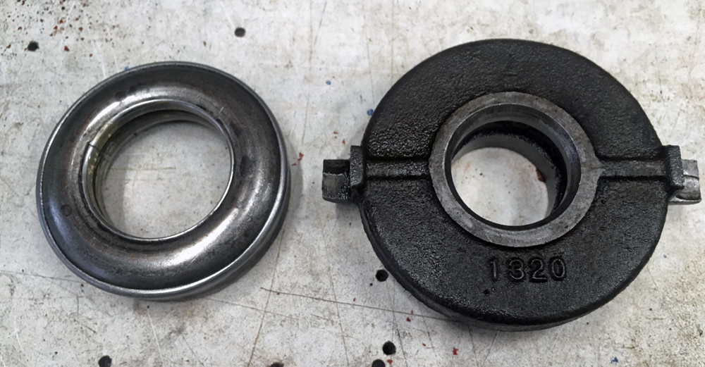
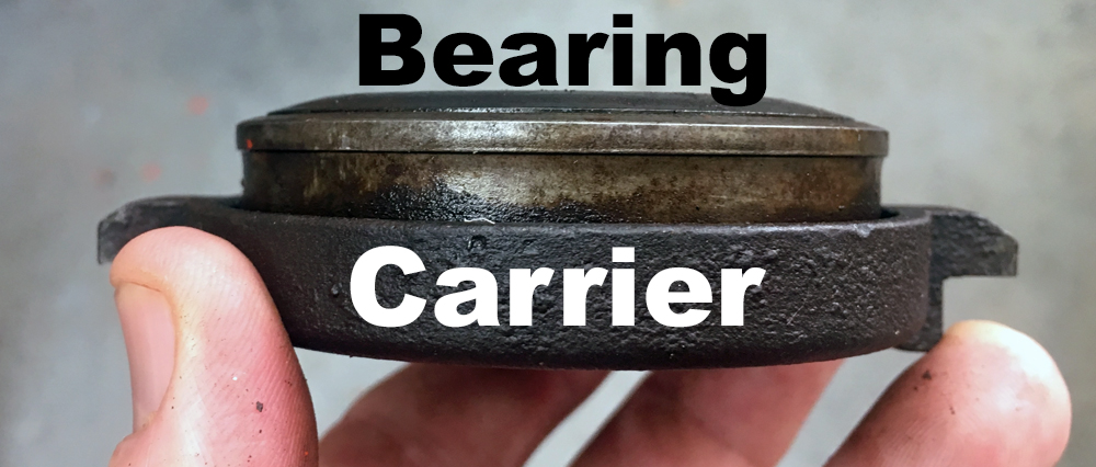
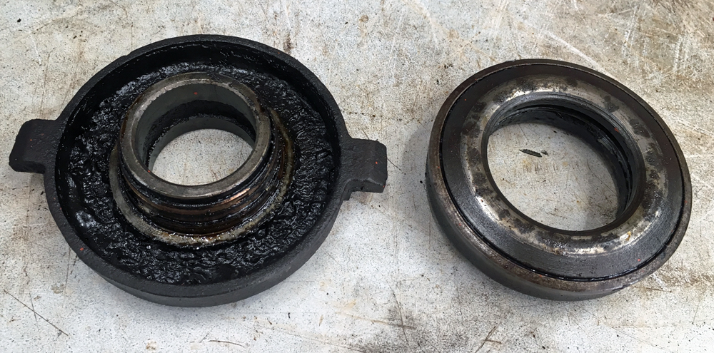
To secure the front bearing, the bearing retainer must be installed. If this is the rear transmission on a dual-trans setup for a Power King / Jim Dandy / Economy tractor, it won’t have a bearing retainer; the center torque tube will do this job.

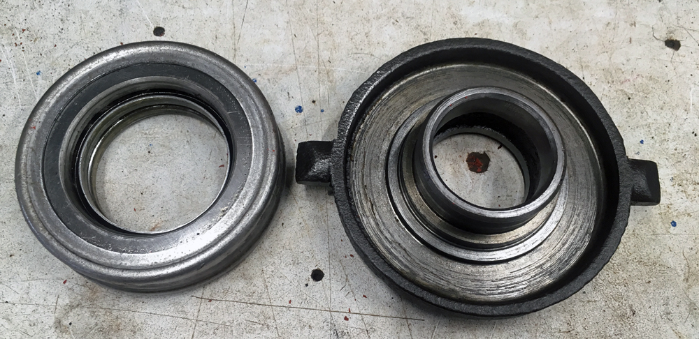
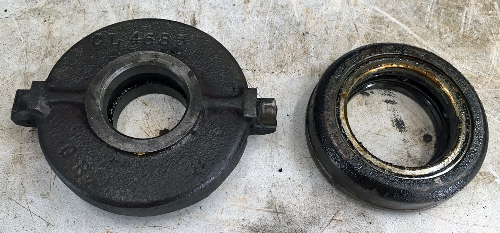
If the bearing retainer has a “divot” inside to help circulate oil, it must be installed over the oil hole in the gear case.

That hole in the gear case lines up with this divot in the bearing retainer.
(Photo © Russ Chastain)

Originally these transmissions used paper gaskets, but I assemble using Permatex silicone gasket maker. Just follow the directions: Tighten the bolts just barely snug, wait at least an hour, then tighten them fully.

I use Permatex gasket maker instead of a paper gasket.
(Photo © Russ Chastain)

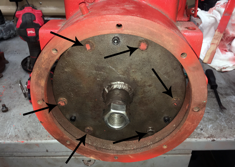
Once installed, the bearing retainer should look like the photo below. Note the position of the oil passage — and that the bearing retainer will also prevent the main countershaft from coming out the front of the gear case.

Bearing retainer installed on t92 transmission.
(Photo © Russ Chastain)

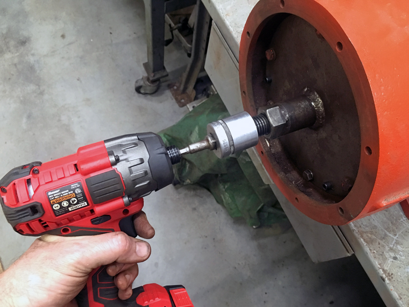
You are just about done, my friend. All that’s left is to install the top shifter assembly. When you do, make sure the shift forks slip into the slots in the sliding gears.

Use a paper gasket or gasket maker to ensure a good seal — but if you’re going to use gasket maker, wait until after you’ve added 8 ounces (no more!) of gear lube. I prefer 85w-140w gear oil.

It’s true that you can always add the lube through the fill hole on the side of the gear case, but it’s much easier to fill from the top while the shifter assembly is off.

Installing the top on a T92 3-speed transmission.
(Photo © Russ Chastain)

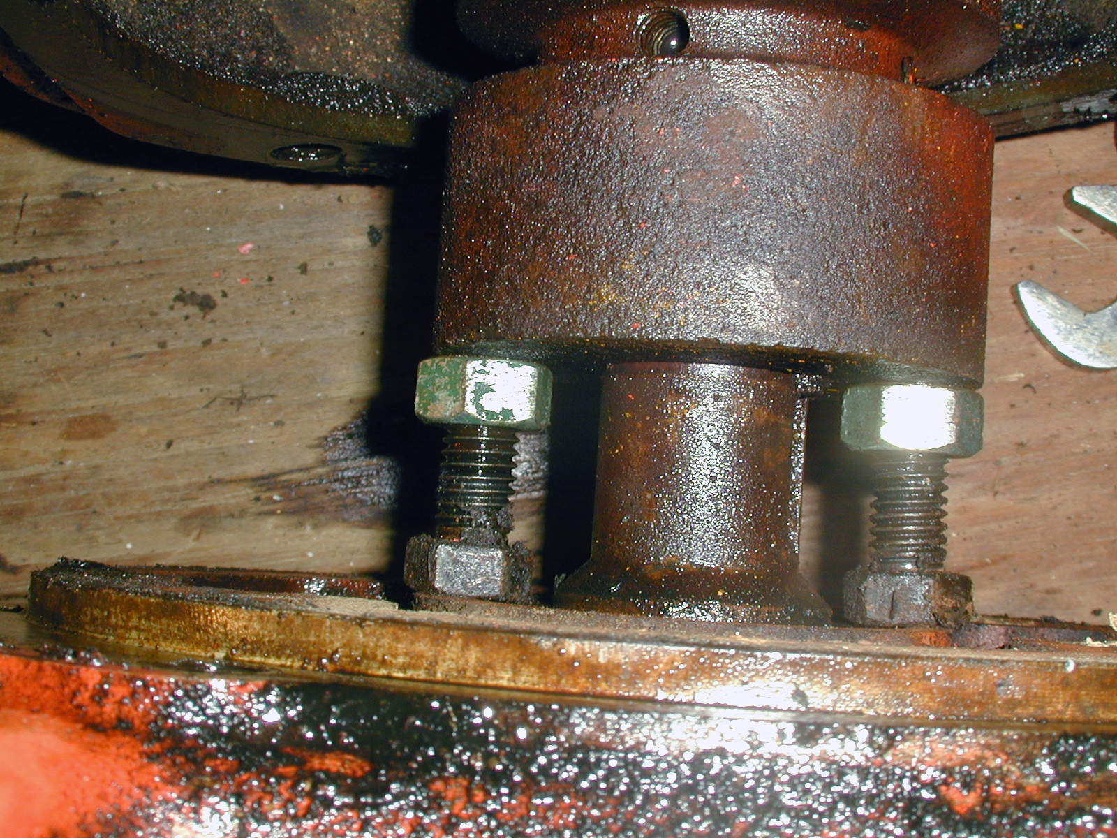
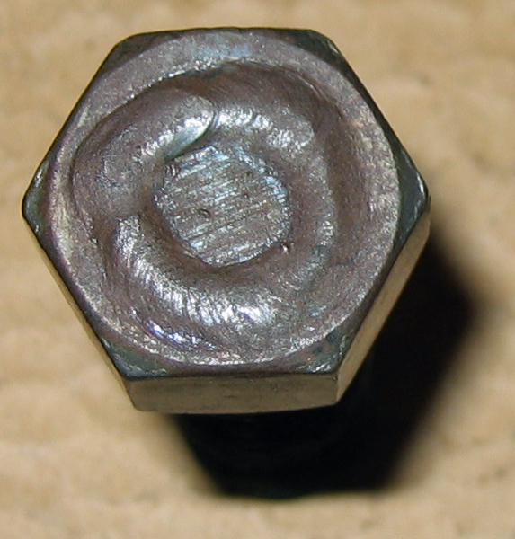
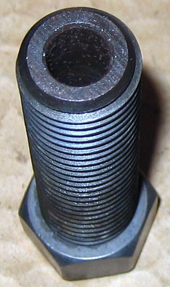
Install your four 5/16″ cap screws (bolts) with lock washers, and you’re done. The longer of the 4 bolts goes into the hole at right rear.

All that’s left is to install bolts in these holes.
(Photo © Russ Chastain)

It’s easy to see why a longer bolt is needed in that location.

Arrow points to the hole where the longer bolt goes.
(Photo © Russ Chastain)

Well, that’s how to rebuild a T-92 transmission gearbox. I hope you found this useful and informative.

— Russ

Throwout Bearing Info for EPCO Power King, Jim Dandy, Economy Steel Body Tractors

Power King tractor throwout bearing.

So you need a throwout bearing for your Power King, Economy, Jim Dandy, Country Squire, or Red-E EPCO tractor? Here’s what you need to know.

There are actually two parts to this throwout bearing: The carrier and the bearing itself.

Power King throwout bearing carrier (right) and bearing. (Photo © Russ Chastain)

It’s not readily apparent that you have a two-piece assembly because they are pressed together, but you should separate the two parts if you need to give your bearing a thorough cleaning and lubrication.

Power King throwout bearing carrier (right) and bearing.
 (Photo © Russ Chastain)

Power King throwout bearing carrier (right) and bearing.
(Photo © Russ Chastain)

Here’s one I pulled out of a tractor and added to my parts stash. For disassembly, you can use a bearing puller to grip the bearing under that lip near the top.

Power King tractor throwout bearing.  (Photo © Russ Chastain)
Power King tractor throwout bearing. (Photo © Russ Chastain)

For a quick and dirty separation for this article, I just gripped the bearing — lightly! — in a bench vise.

 Dissassembling a Power King tractor throwout bearing.  (Photo © Russ Chastain)
Dissassembling a Power King tractor throwout bearing. (Photo © Russ Chastain)

Then I lightly tapped on the inside portion of the carrier, which is that middle ring my hammer is touching in this picture. This allowed me to drive the carrier out of the bearing.

Dissassembling a Power King tractor throwout bearing.  (Photo © Russ Chastain)
Dissassembling a Power King tractor throwout bearing. (Photo © Russ Chastain)

This exposed gunk I couldn’t have cleaned out without taking it apart.

Throwout bearing carrier (left) has a bunch of gunk in it.  (Photo © Russ Chastain)
Throwout bearing carrier (left) has a bunch of gunk in it. (Photo © Russ Chastain)

I like to keep using anything that’s still usable, and I hate to waste anything. For this reason, I will soak these parts in kerosene/diesel fuel to dissolve all the old crud, thoroughly rinse with same, then lubricate the bearing with bearing grease by forcing it into the bearing.

 Throwout bearing and carrier (left).  (Photo © Russ Chastain)
Throwout bearing and carrier (left). (Photo © Russ Chastain)

This is assuming the carrier is not overly worn where the clutch fork rides against it, and the bearing is in good shape mechanically & spins freely under pressure when it’s clean.

To reassemble, press the two parts together carefully, making sure they are square with one another. A bench vise makes a reasonable “press” for doing this.

If you wish to replace instead of reusing or if your bearing is beyond repair, you can buy a new one. The part number is Federal-Mogul C-1697-C, and this gets you the bearing and carrier. Just be careful while shopping; some throwout bearings listed under this number are quite different. Make sure it looks like those pictured here.

A new throwout bearing in the box.  (Photo © Russ Chastain)
A new throwout bearing in the box. (Photo © Russ Chastain)

Here’s a link to the best price I could find: Buy a Power King tractor throwout bearing

Good luck and thanks for reading.

— Russ

How to Remove Clutch Flywheel on EPCO Power King, Jim Dandy, Economy Steel Body Tractors

The nut & bolt method of removing Power King clutch flywheel.


If you need to pull your tractor’s engine apart to work on it, you will probably want to remove the clutch flywheel from the rear end of the crankshaft. There are several ways to do this, but the first thing you need to know is this: DO NOT USE A JAW PULLER ON THE CLUTCH FLYWHEEL. The flywheel WILL break.

Usually, the clutch flywheel will be stubborn and won’t want to come off. The second clutch flywheel I ever removed was my first stubborn one. I learned that this is the rule rather than the exception…. they are usually stuck on there good.

First Step

Remove the set screws securing the flywheel to the crankshaft. Don’t just loosen them; remove them entirely. There are two threaded holes, and sometimes each hole will have two set screws, one on top of the other. Make sure all the screws are out of there, and squirt some penetrating oil into the holes.

I have a cheap set of T-handle allen wrenches that work well for removing the set screws. (Photo © Russ Chastain)
I have a cheap set of T-handle allen wrenches that work well for removing the set screws.
(Photo © Russ Chastain)

Use a 5/32″ allen wrench to remove the set screws. Make sure the hex-shaped hole is nice and clean before inserting the hex wrench. A small-bladed screwdriver is handy for that.

I like to tap the wrench in lightly with a hammer to ensure it goes all the way into the hole. This greatly reduces the chance of stripping the hex hole in the set screw, which would be tragic.

Tap the wrench lightly with a hammer to be sure it's fully inserted in the set screw. (Photo © Russ Chastain)
Tap the wrench lightly with a hammer to be sure it’s fully inserted in the set screw.
(Photo © Russ Chastain)

Ready to pull a set screw. (Photo © Russ Chastain)
Ready to pull a set screw.
(Photo © Russ Chastain)

Remove the screws entirely, so you can check for a second set screw below the first and get some penetrating oil onto the crankshaft through the screw hole.

Set screw success. (Photo © Russ Chastain)
Set screw success.
(Photo © Russ Chastain)

Nut & Bolt Method

I used a method that was suggested by a fellow PKer, and since that was back in 2004 I have no clue who it was. It’s a simple — but tedious — process. First, you remove the 4 bolts holding the clutch flywheel housing to the engine, and get that housing free so you can get to the area between flywheel and engine.

Remove the set screws securing the flywheel to the crankshaft. Don’t just loosen them; remove them entirely. There are two threaded holes, and sometimes each hole will have two set screws, one on top of the other. Make sure all the screws are out of there, and squirt some penetrating oil into the holes.

The nut & bolt method of removing Power King clutch flywheel.
(Photo © Russ Chastain)

Find a pair of bolts & nuts that will fit between the flywheel and engine. In my case it was a 1969 Jim Dandy with a Kohler K301 engine, but that’s not important. The bolts will act as screw jacks, which will place considerable pressure on your engine block. It may be wise to place some steel flat bar between the bolt heads and the engine. I did this at a later stage.

Close-up of the nut & bolt method of removing Power King clutch flywheel.
(Photo © Russ Chastain)

Simply use two wrenches and screw the nuts off of the bolts a little at a time, alternating between them to keep things even. You will run out of bolt before you’re done… that’s when you find longer bolts or use more/thicker spacers between bolts & engine. In the photo above, you can see that the flywheel has already moved away from the engine a little bit.

Fancy Custom Puller

Once I started working on PKs regularly, I decided to spring for a sure-nuff flywheel puller. I bought this custom puller made for and sold by the late Jerry Frank of Texas (USSUPPLY).

Specialized custom puller for pulling EPCO clutch flywheels.
(Photo © Russ Chastain)

Specialized custom puller for pulling EPCO clutch flywheels.
(Photo © Russ Chastain)

Specialized custom puller for pulling EPCO clutch flywheels.
(Photo © Russ Chastain)

You remove the clutch fingers, pressure plate, and clutch disk, and bolt this to the flywheel using the six threaded holes in the flywheel normally used for attaching the clutch assembly.

Specialized puller, installed on a clutch flywheel. Arrows indicate bolts holding puller to flywheel. I use 6 of the 8 bolts from the clutch pedal housing. (Photo © Russ Chastain)
Specialized puller, installed on a clutch flywheel. Arrows indicate bolts holding puller to flywheel. I use 6 of the 8 bolts from the clutch pedal housing.
(Photo © Russ Chastain)

Then you use the threaded center puller bolt with various lengths of round rod inserts. I place a socket on the hex nut and tighten it with an impact gun, and the flywheel usually comes right off.

I use an impact gun with this puller, after fully removing all set screws and securing the puller to the flywheel. (Photo © Russ Chastain)
I use an impact gun with this puller, after fully removing all set screws and securing the puller to the flywheel.
(Photo © Russ Chastain)

Be careful not to let the flywheel get away from you, because it’s heavy. Once it comes free of the crankshaft, it’s gonna want to succumb to gravity’s pull.

Custom puller attached to a flywheel that's been pulled. (Photo © Russ Chastain)
Custom puller attached to a flywheel that’s been pulled.
(Photo © Russ Chastain)

Simple Homemade Puller

After I bought that expensive puller, I learned about this homemade puller that was made by a fellow PKer.

Simple homemade EPCO clutch flywheel puller

Simple homemade EPCO clutch flywheel puller

Official EPCO Puller

I’m told this puller was an “official” tool from EPCO — or as official as they ever got.

"Official" EPCO clutch flywheel puller
“Official” EPCO clutch flywheel puller

Like my puller, it attaches to the threaded holes for the clutch.

Drill & Tap for a Bolt-Type Puller

Some folks have been known to drill & tap new holes in the “meaty” central portion of a clutch flywheel so they can use a bolt-type puller (like you’d use to pull a Kohler engine flywheel).

In Closing

These are certainly not the only methods that will work, but hopefully they will give you some ideas.

I hope you found this helpful! Feel free to comment below.

– Russ